Thanks to Ian Mason (http://willowracing.blogspot.com) and Zhou (RGMCN) for this new model. It is always a pleasure to bring them to life.
Getting a Harrier, the new model from Ian/Zhou, was an obvious choice after having so much fun with my E-Willow Sor last year.
As with my other models, I do not compete (yet).
So I make “portable” f3f model. I electrify to be able to fly it more easily everywhere when I take holidays to leave Paris and go in the Alps or by the seaside. The purpose of the motor is not to make a hotliner.
I followed recommendations from Ian on servos and his build notes. It is pretty similar to previous models provided by Zhou and Ian like the willow sor.
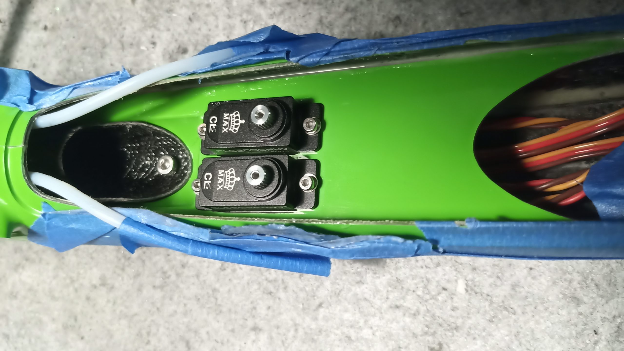
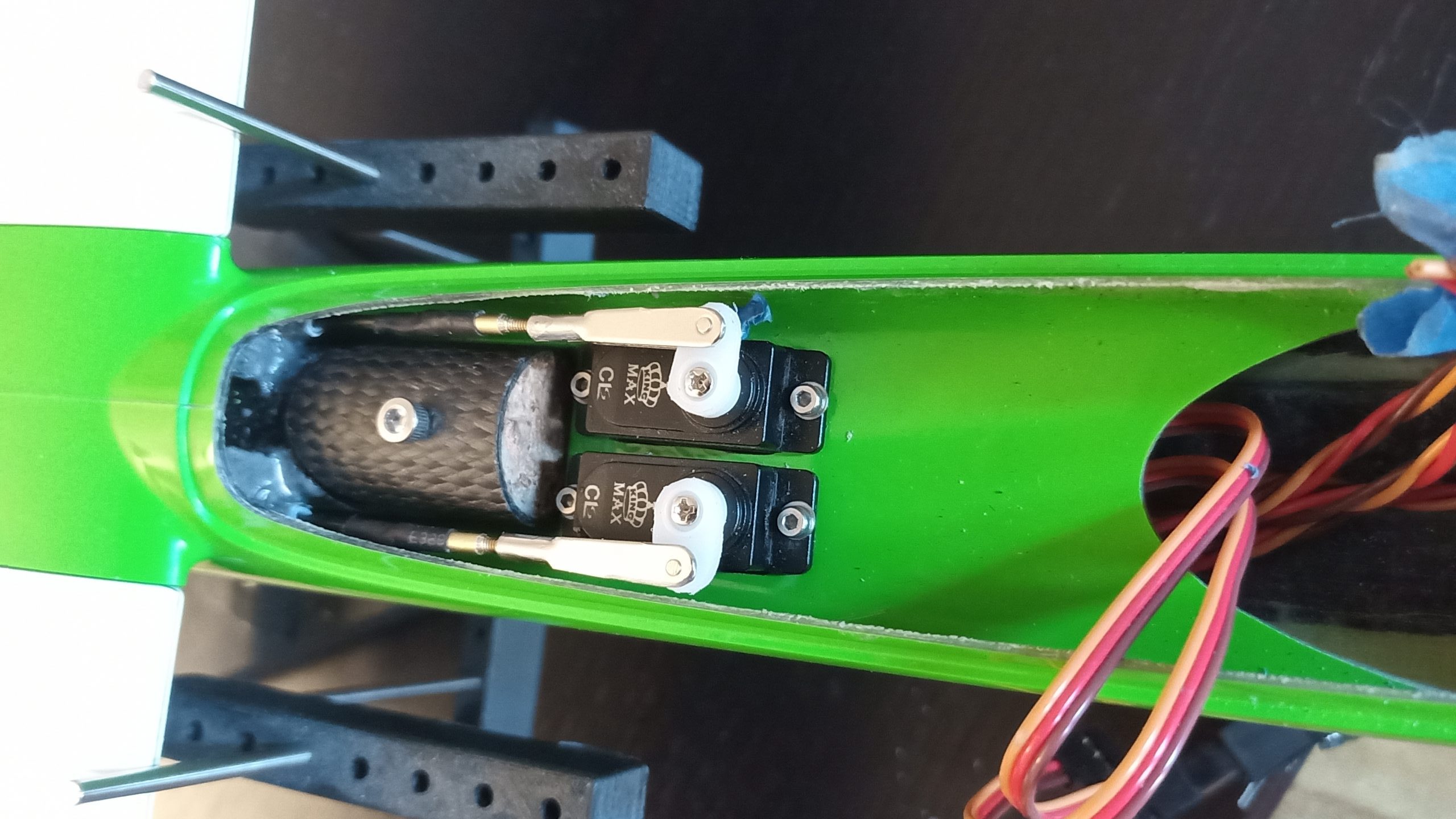
- Kingmax servos
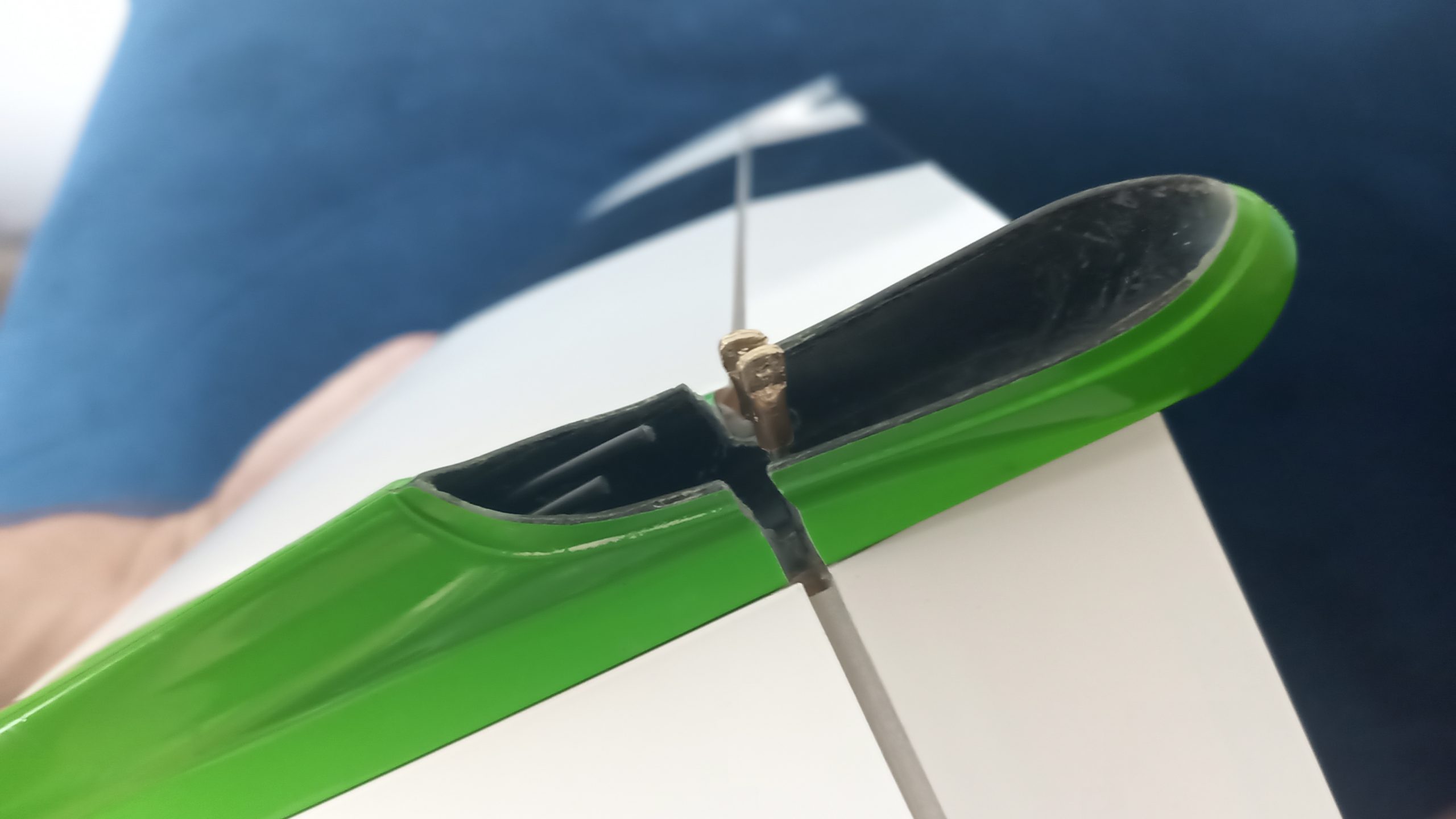
- Clevis and horn install under the skin – seamless
- 3d printed w/ bearing servo frame
- Brushless direct drive sunnysky x2220-iii 980kv
- 3s Lipo 2200 mah
- 12×6 propeller
This motor configuration was already tested. My E-Willow has the same and the climb rate is good. The ammeter gets 29Amp at 12.1V – 350 Watts. The Harrier fully loaded is 2.7 Kg… 130 real Watts per Kg.
As a reference, an acceptable climb rate of a sailplane is commonly reached at 100 W/Kg.
Quick links:
Wings
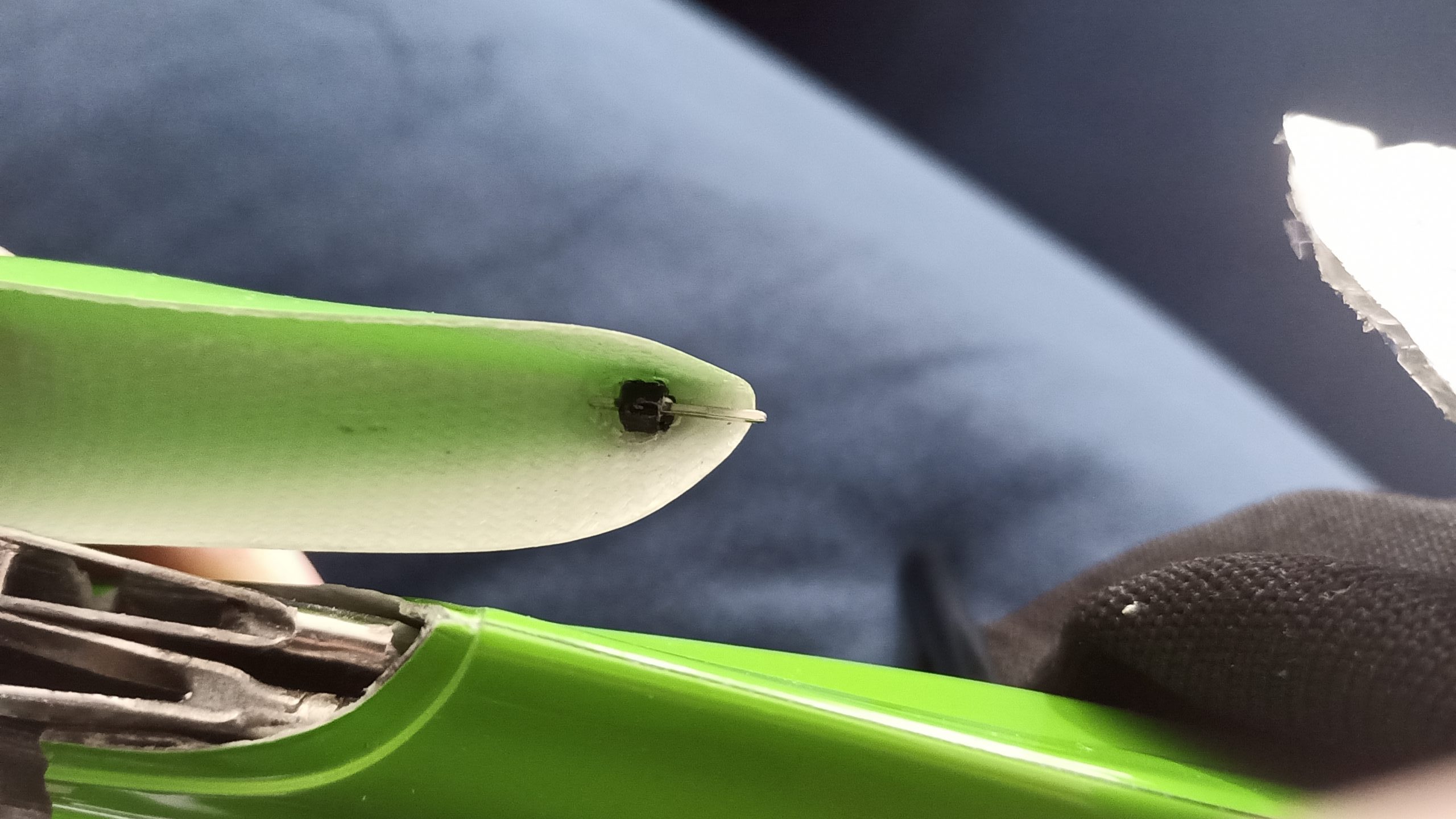
Following Ian’s advice (build notes), I asked Zhou to omit the horn from the aileron/flap. I decided to complete a seamless installation without any commercial LDS/IDS system.

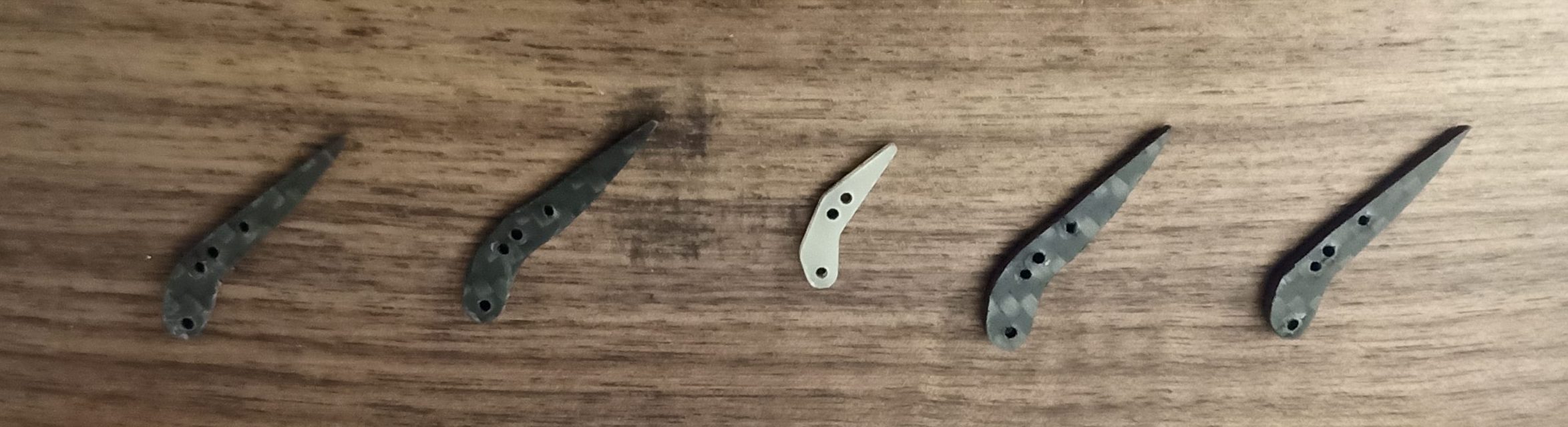
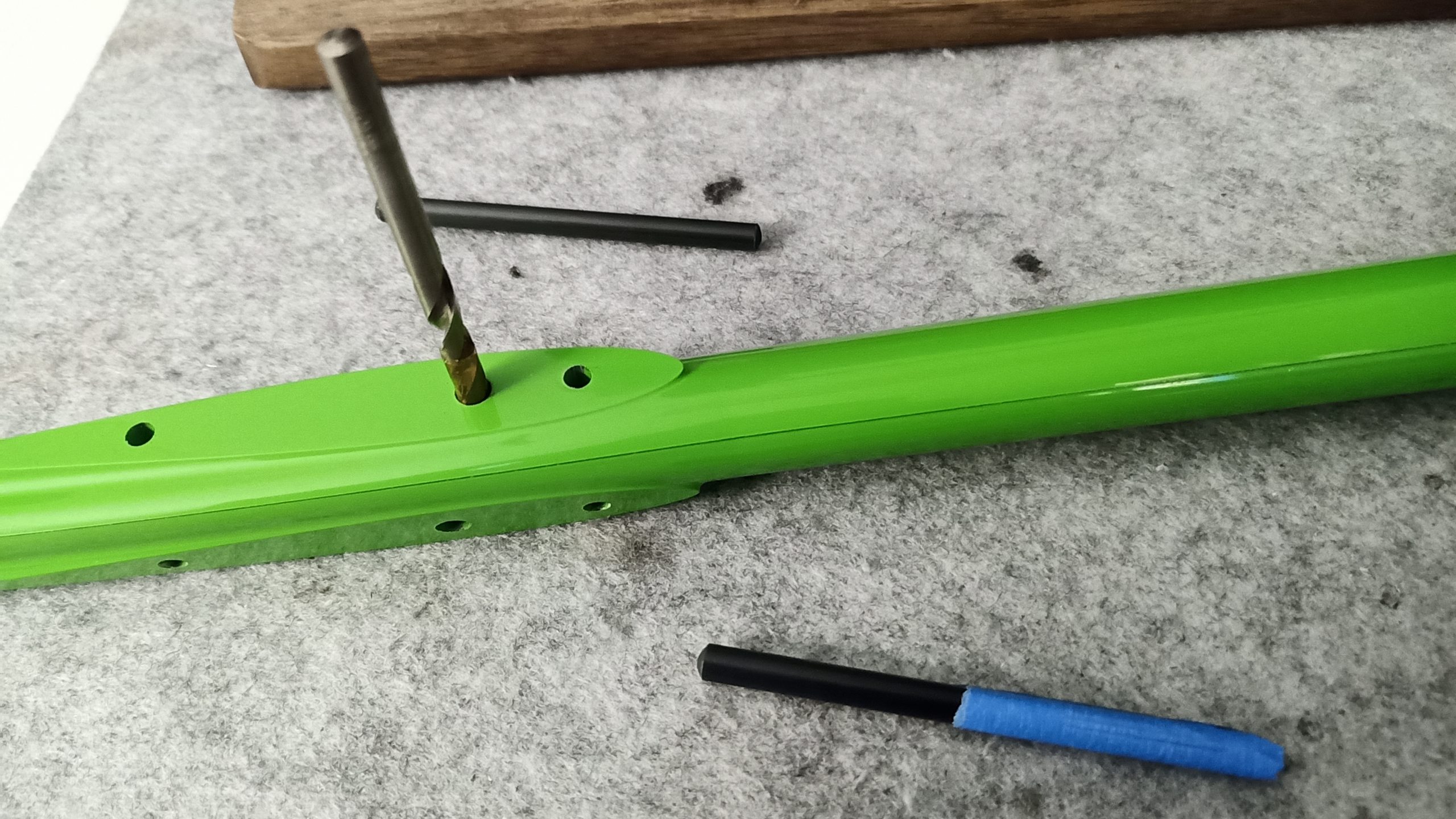
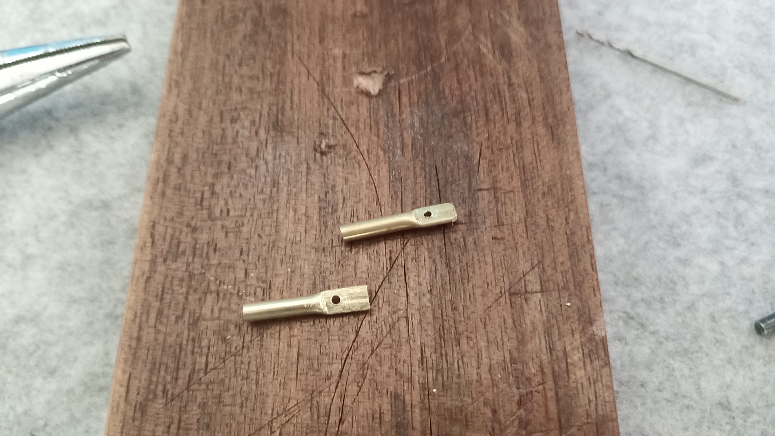
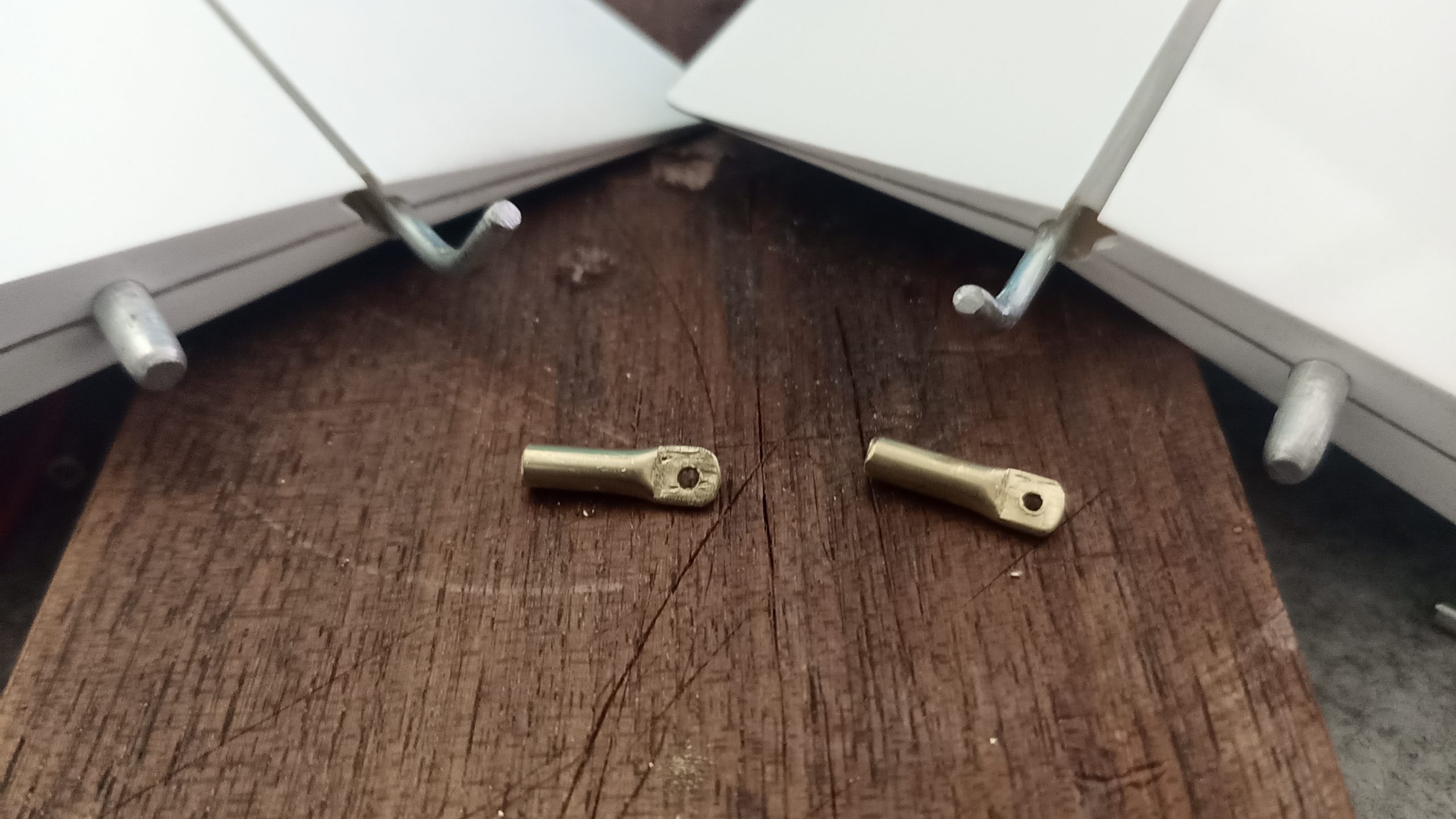
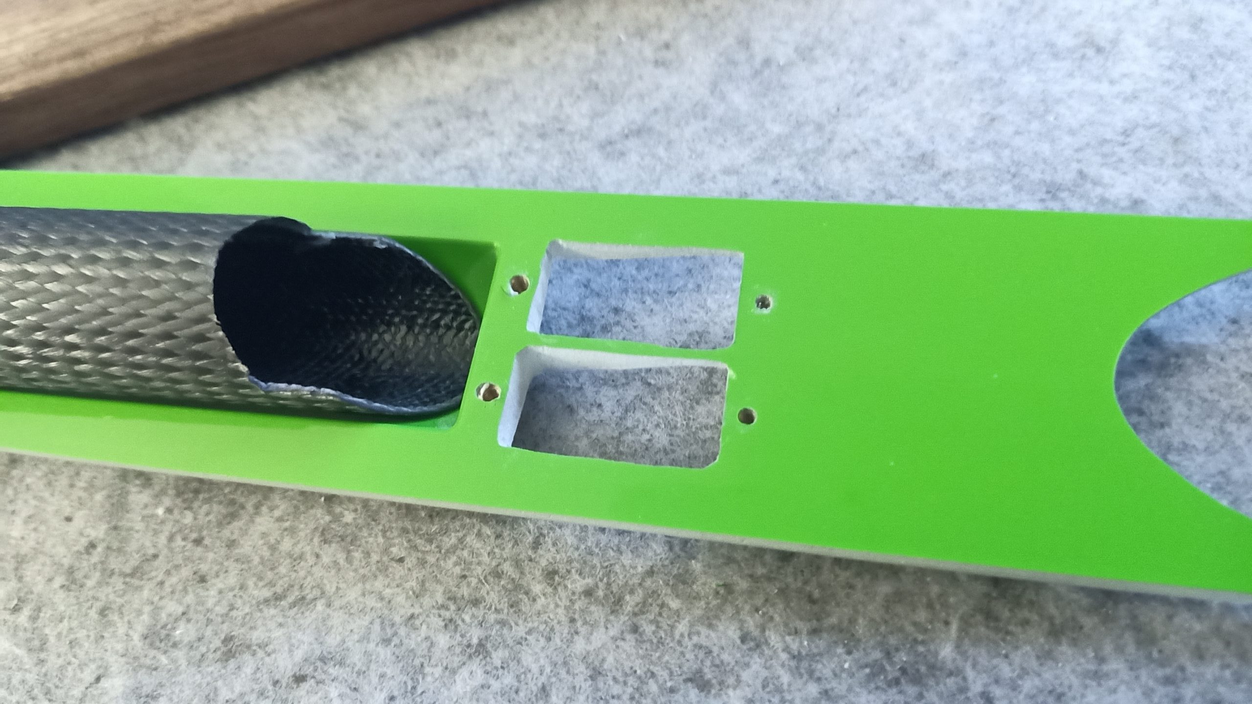
Take 4 mini plates, hold them together, make a first hole (the horn hole: 1.5mm), fix the 4 plates + the provided (fiberglass) horn with a spare 1.5mm drill bit.
Replicate the two spare holes and shape the rest of the horns.
The position of the two holes are a perfect reference for the position of the horn in the aileron/flap (first hole flush for the aileron, second hole flush for the flap)

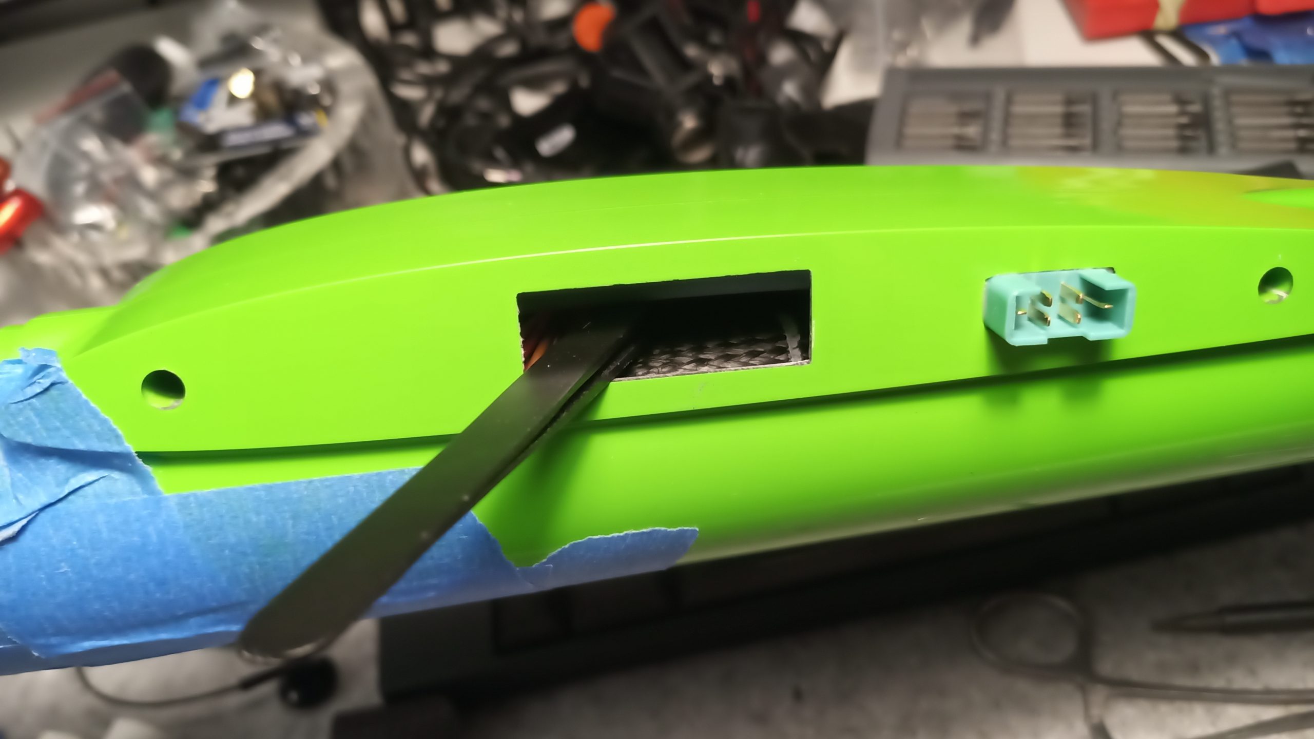
Glue the carbon horn to the wing. You can add a small rod in one of the holes, it will lay flat on the bottom of the surface. This allows two things: to set it exactly at the right position and to reinforce the bonding with the expoxy.
Ensure to have the good travel. To keep a nice servo precision, it needs to cover at least 70% of its range to move the surface around recommended settings from Ian.
For my setup, I got on 5mm of horizontal travel for the aileron and 11mm travel for the flap (nearly reaching 80 degrees angle fully open and a small upper movement).
The same movement amplitude is needed on the servo and you can easily replicate when preparing the servo arm and trimmed clevis.
When looking for lower travel, more stiffness is needed to reach a slope free assembly:
use metal, fill micro gaps between arm hole and clevis with cyano (use super glue accelerator and break the fresh bonding manually), cyano the clevis and the threaded rod.
Servo frames are on my Github (fully parametric) and ready to print.


Same with flaps.
Tail
Round the carbon rod to make it like the drill bit end.
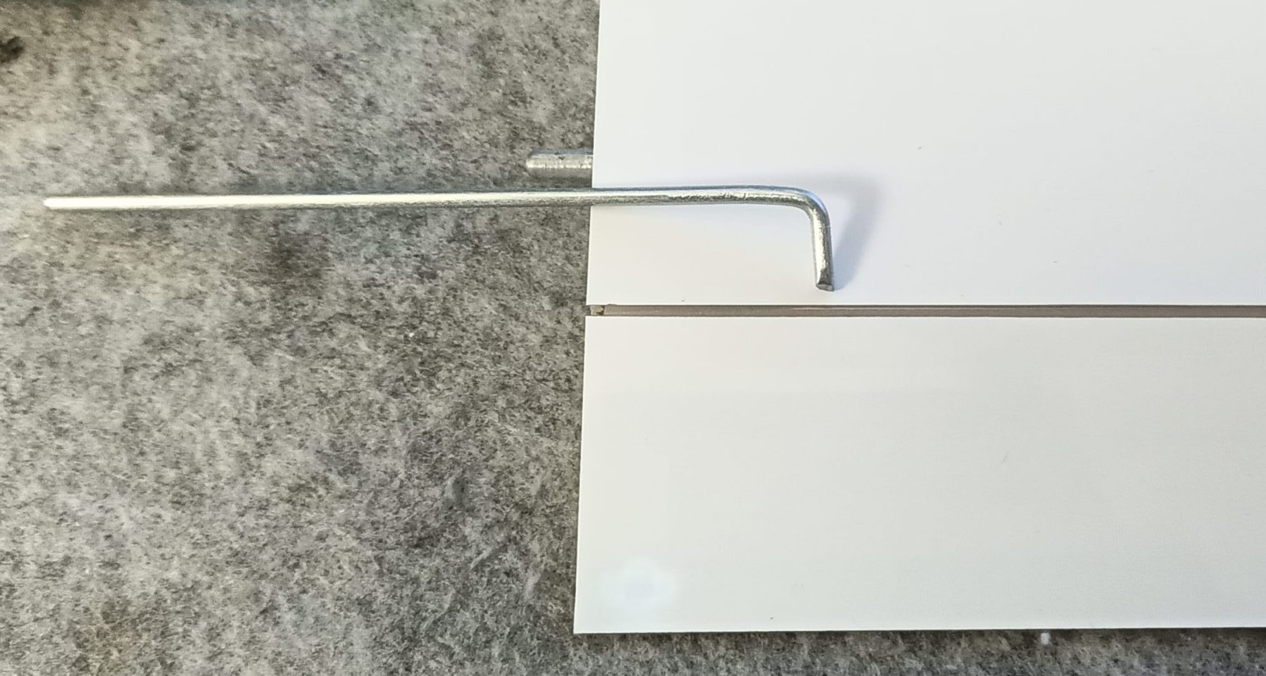
Make the end a bit cutting.
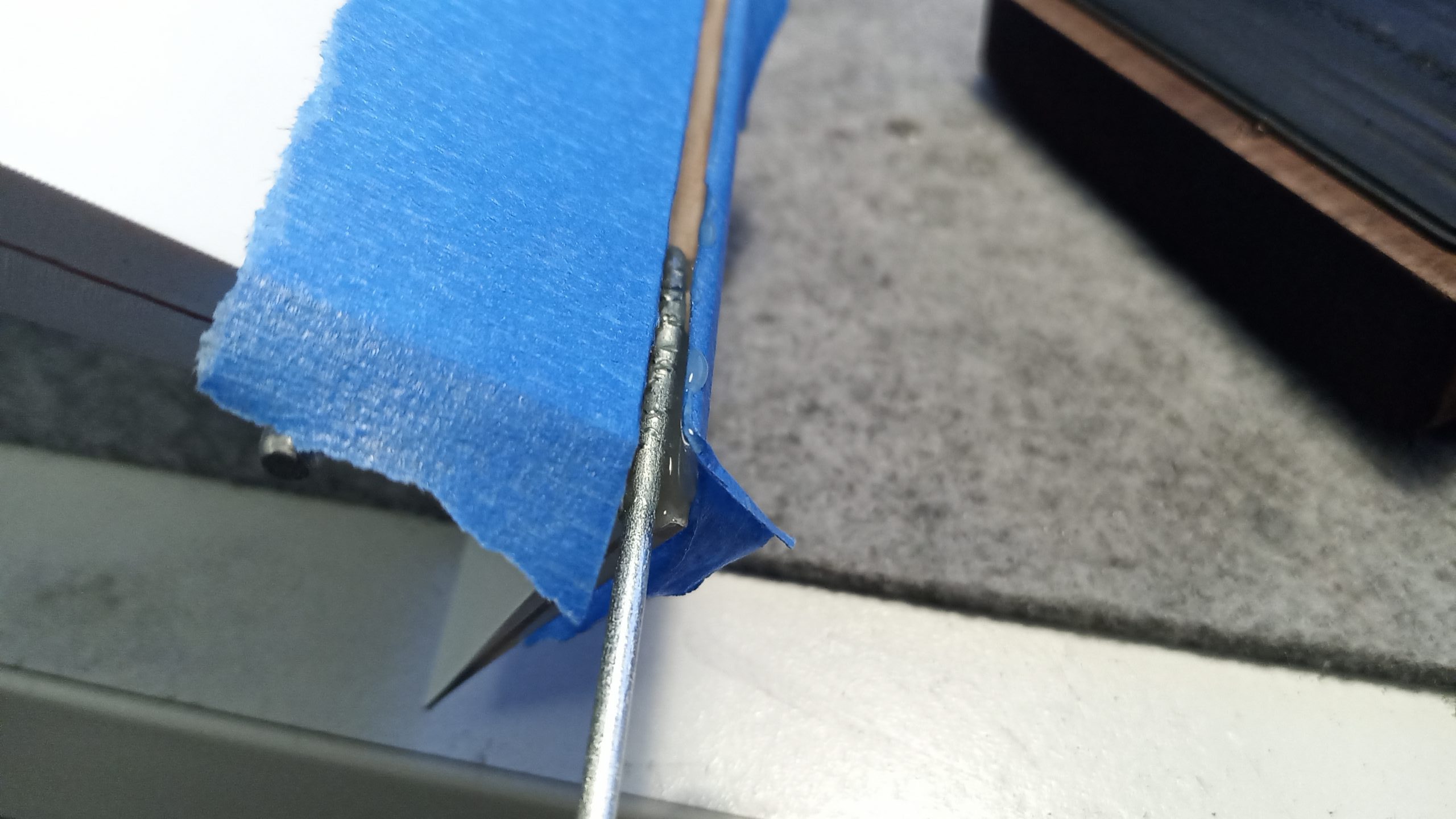
Make some nicks with cutting pliers. Drown it in slow epoxy (hole, surface).
Don’t put epoxy on the hinge!
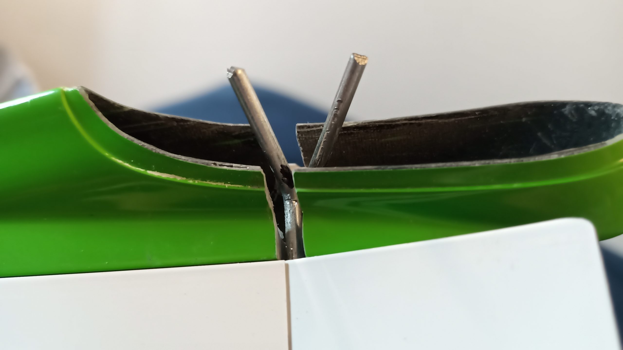
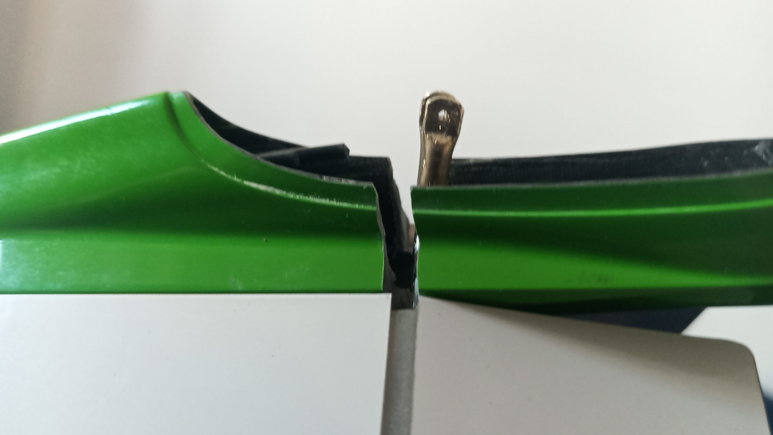
The carbon pushrod should have no vertical tension to reach the hole.
Fuselage – Electric
I got a non-electric fuselage which I cutted to 31mm diameter section.
As with my other fuselage, with the extra weight of the brushless motor + a bit more lead, I reinforced with carbon. The full fiberglass fuselage part (under the canopy) received 3 carbon cloth strips going from wing root to the nose. I use redundant frsky 2.4Ghz + r9 900MHz receivers, carbon is not a problem.
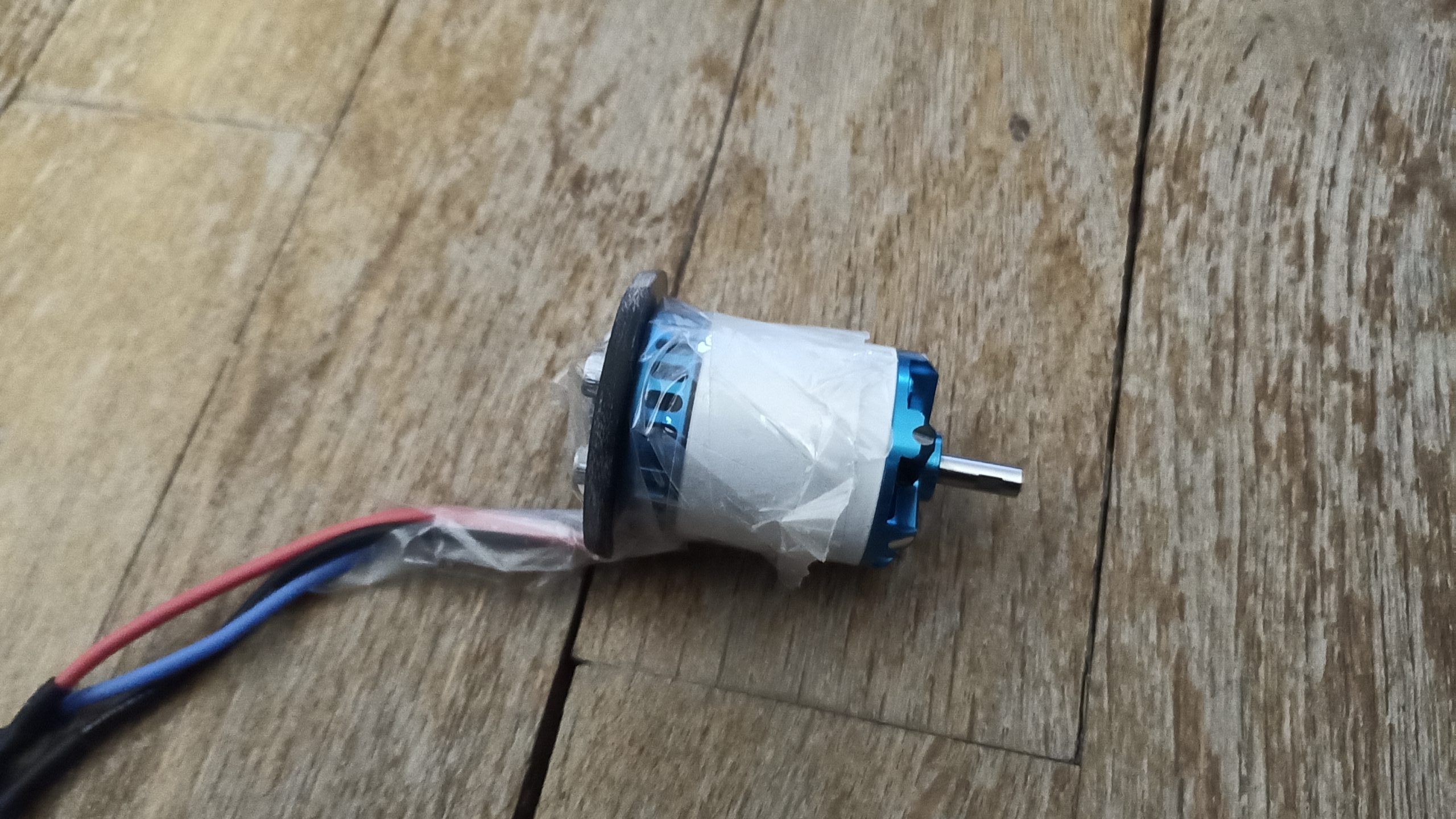
The sunnysky motor has been inverted like my others build (willow and e-schwing)
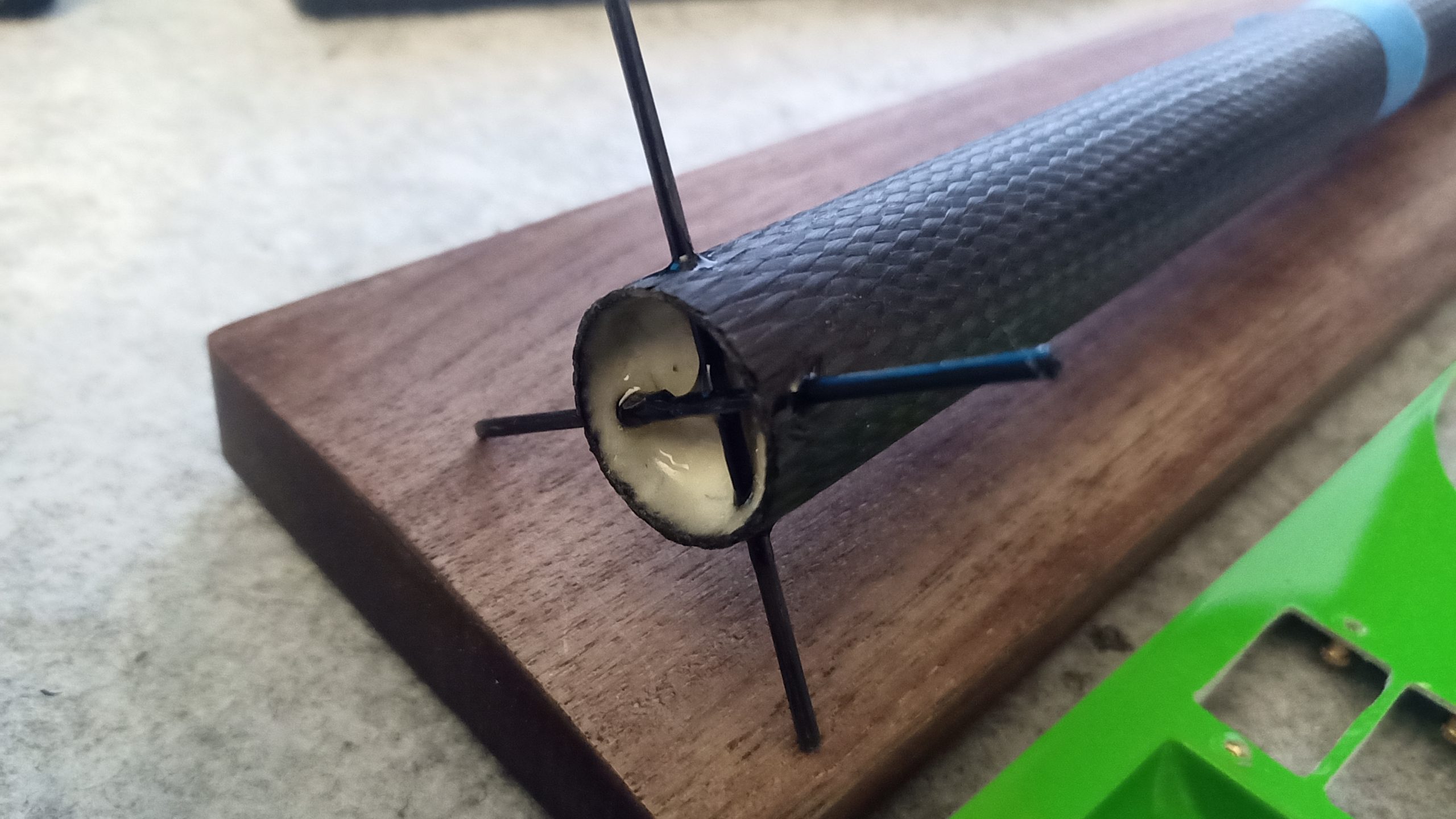
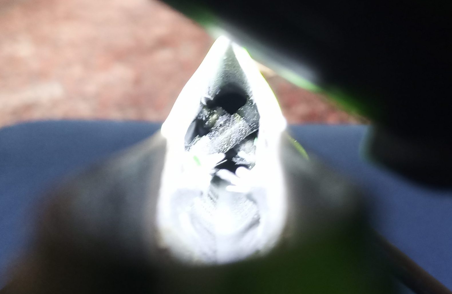
Ended with a 10mm section of a cork stopper, filled with epoxy and microballoon filler.
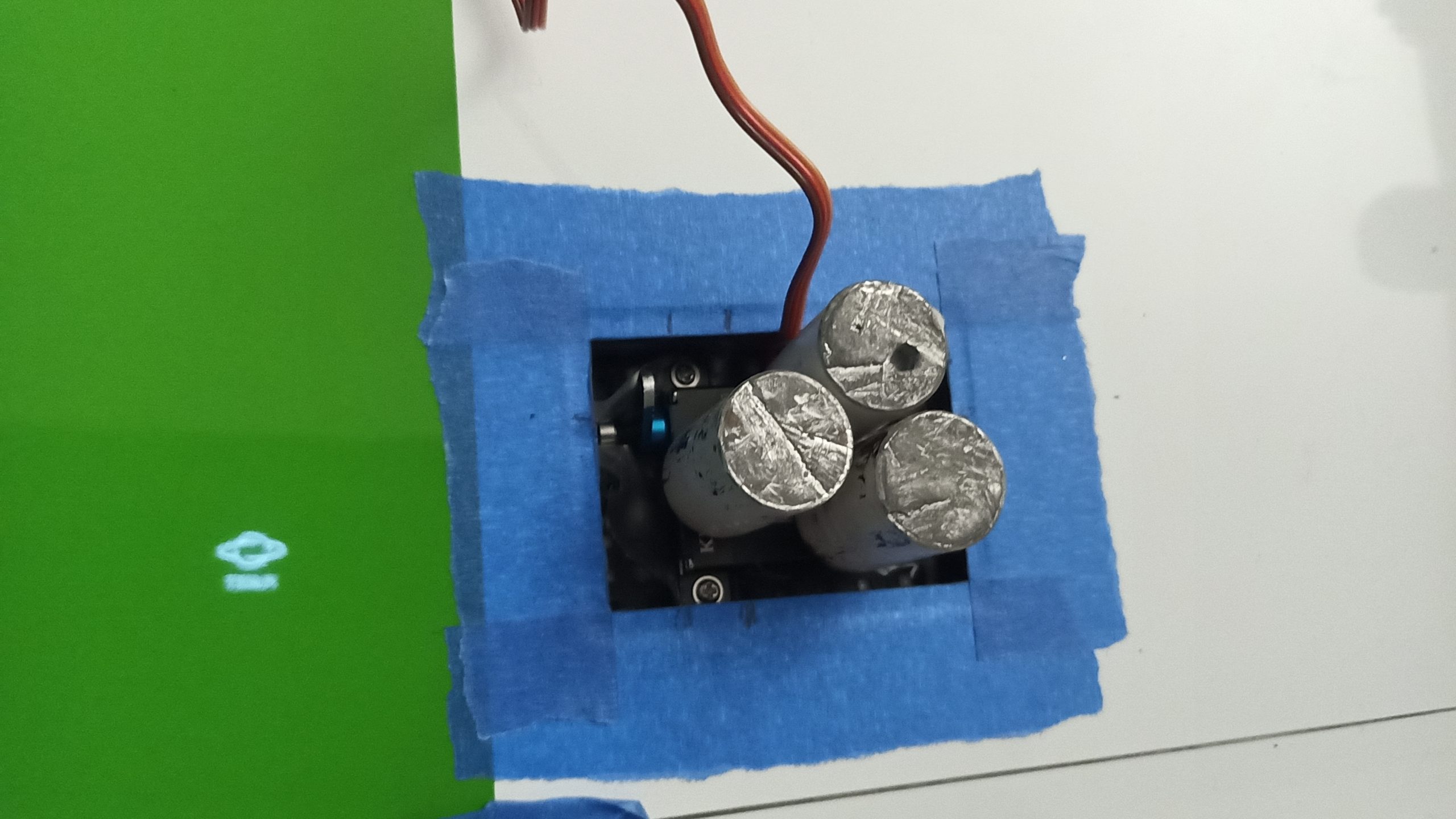
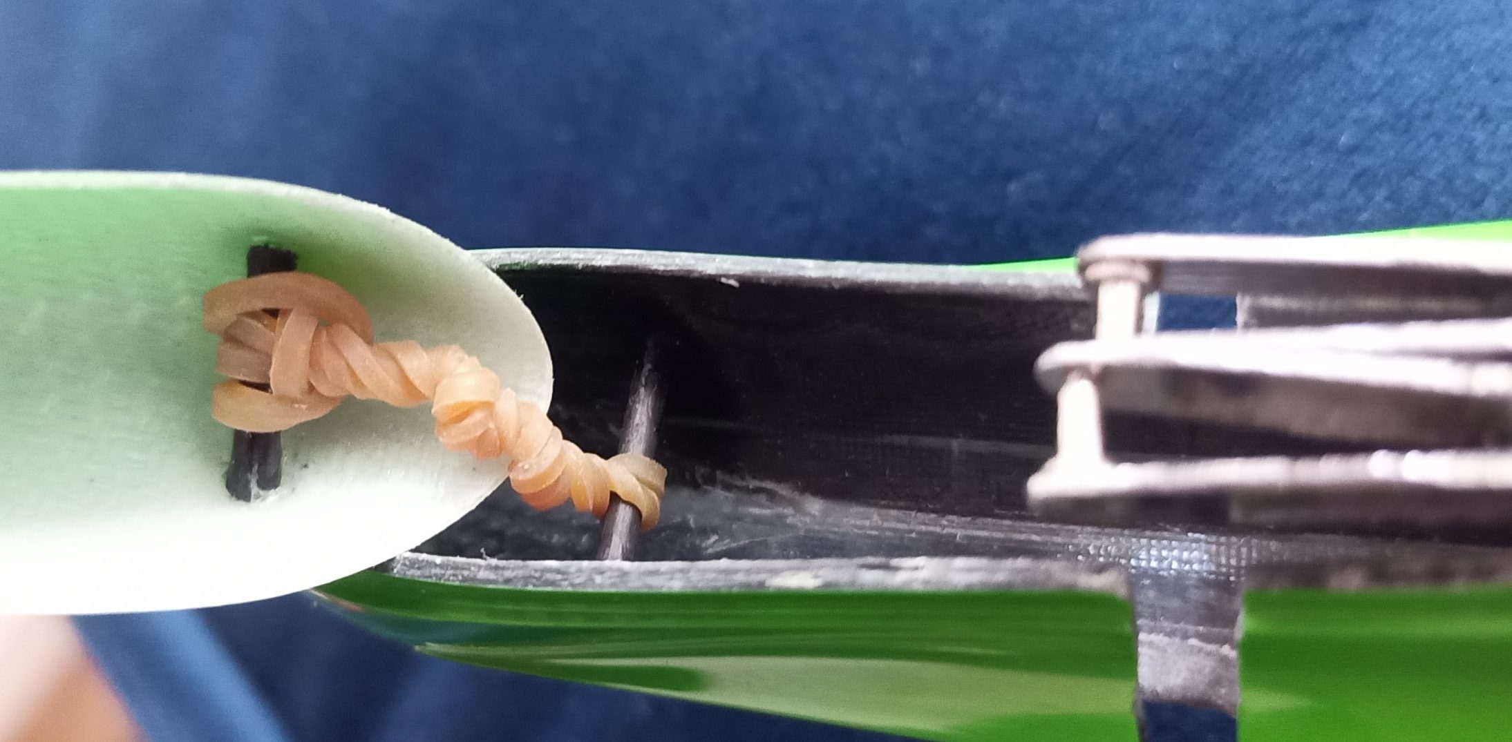
To secure the tube end, center and stabilize it perfectly in the fuselage, I add 2/3mm push rod parts to cut to the exact fit when adjusting the parts.
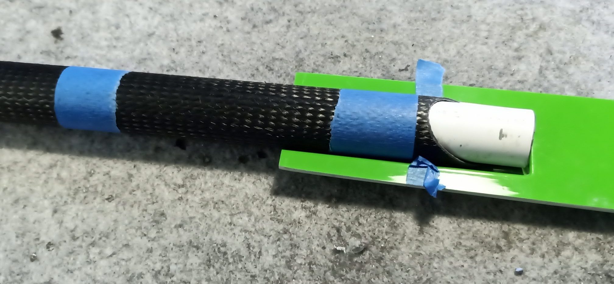
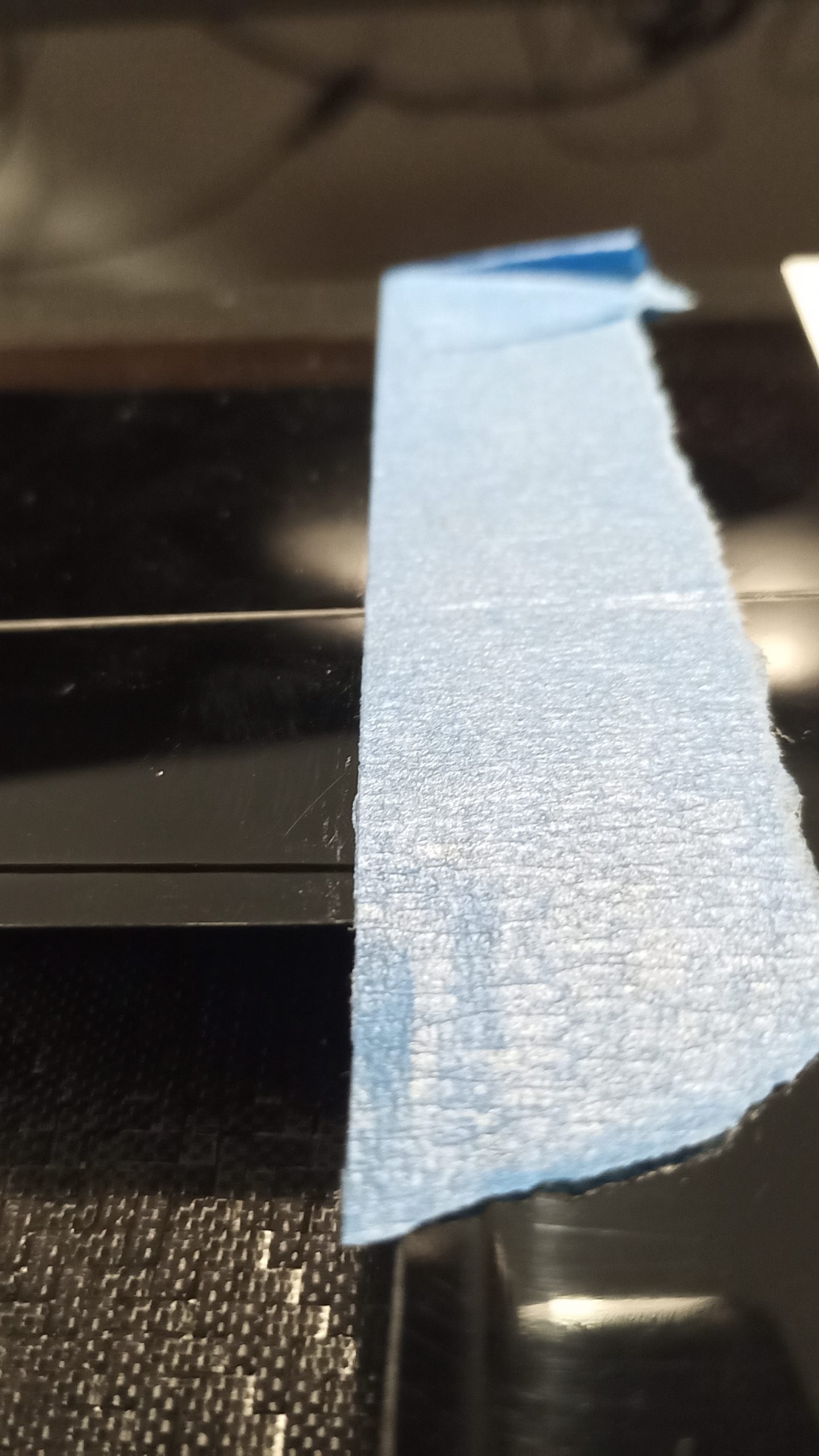
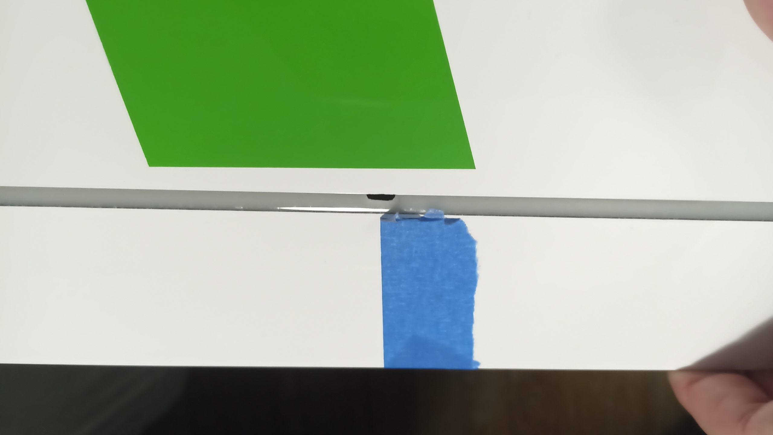
The left blue tape is my CG of the tube (when loaded with my 7 lead slugs) – It will need to be perfectly aligned with the targeted CG of the Glider.
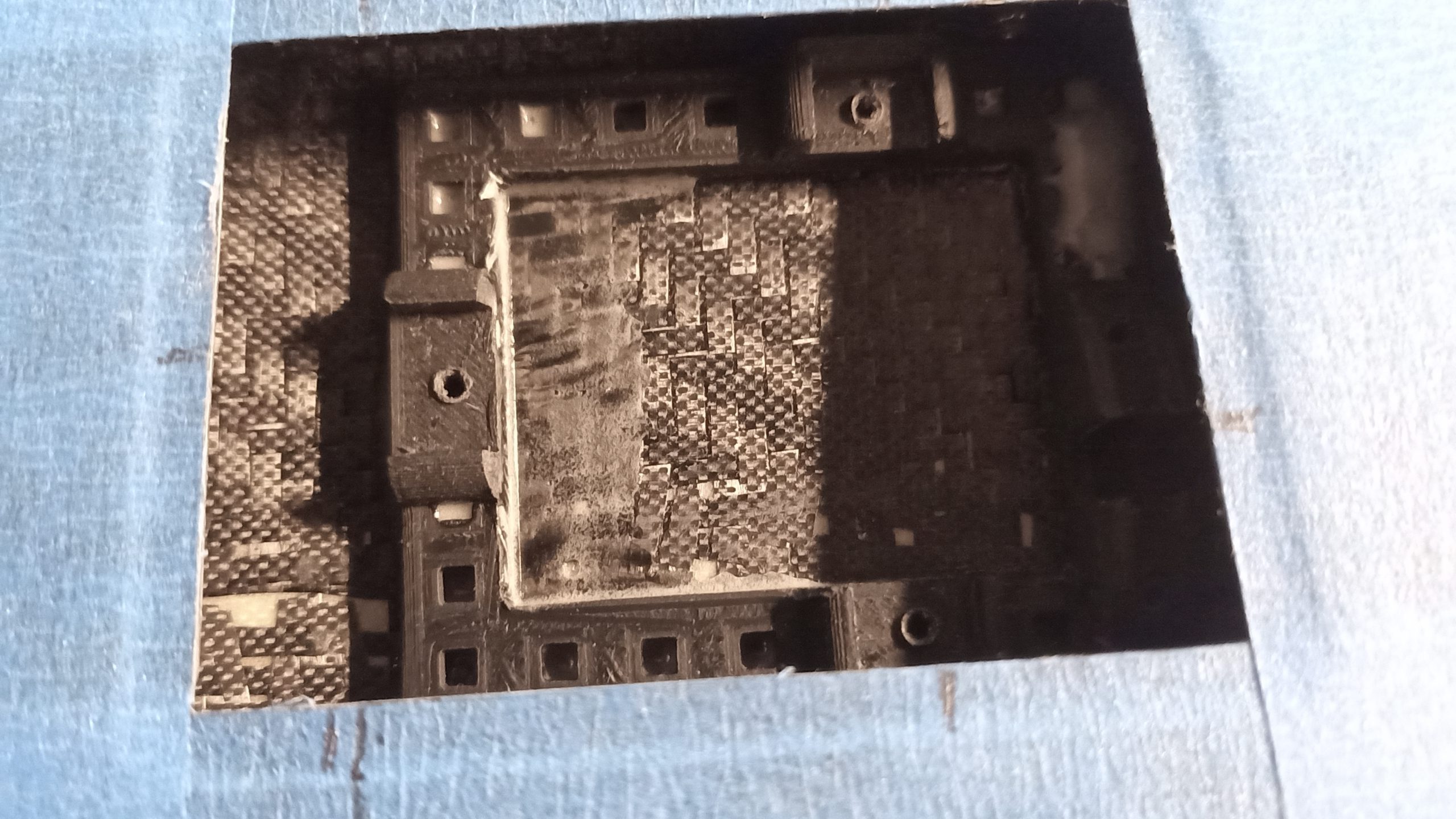
The Electric version is more tricky I guess – it needs space for a bit more lead behind the motor firewall and a bigger lipo. The servo plate is pushed as far as possible – all depends of the ballast tube CG and still beeing able to put/recover slugs in the tube.
provided by Ian. A plier helps to secure the wires and pushrod from the glue. It also guarantees the ballast tube is not in the way of the wing joiner.
The other end of the rod is wrapped with epoxy wet fiberglass cloth before introduced in the fuselage.
The tube is glued on the servo plate also and a nut is securing the cork of the slugs. The servo plate has an underneath nut.
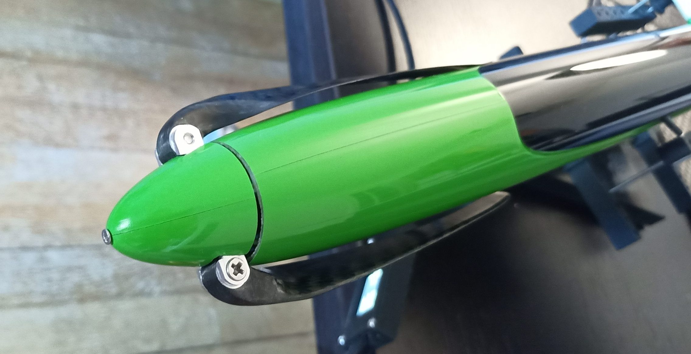
underneath is a simple Gemfan aluminium CNC spinner mounted with carbon prop 12×6
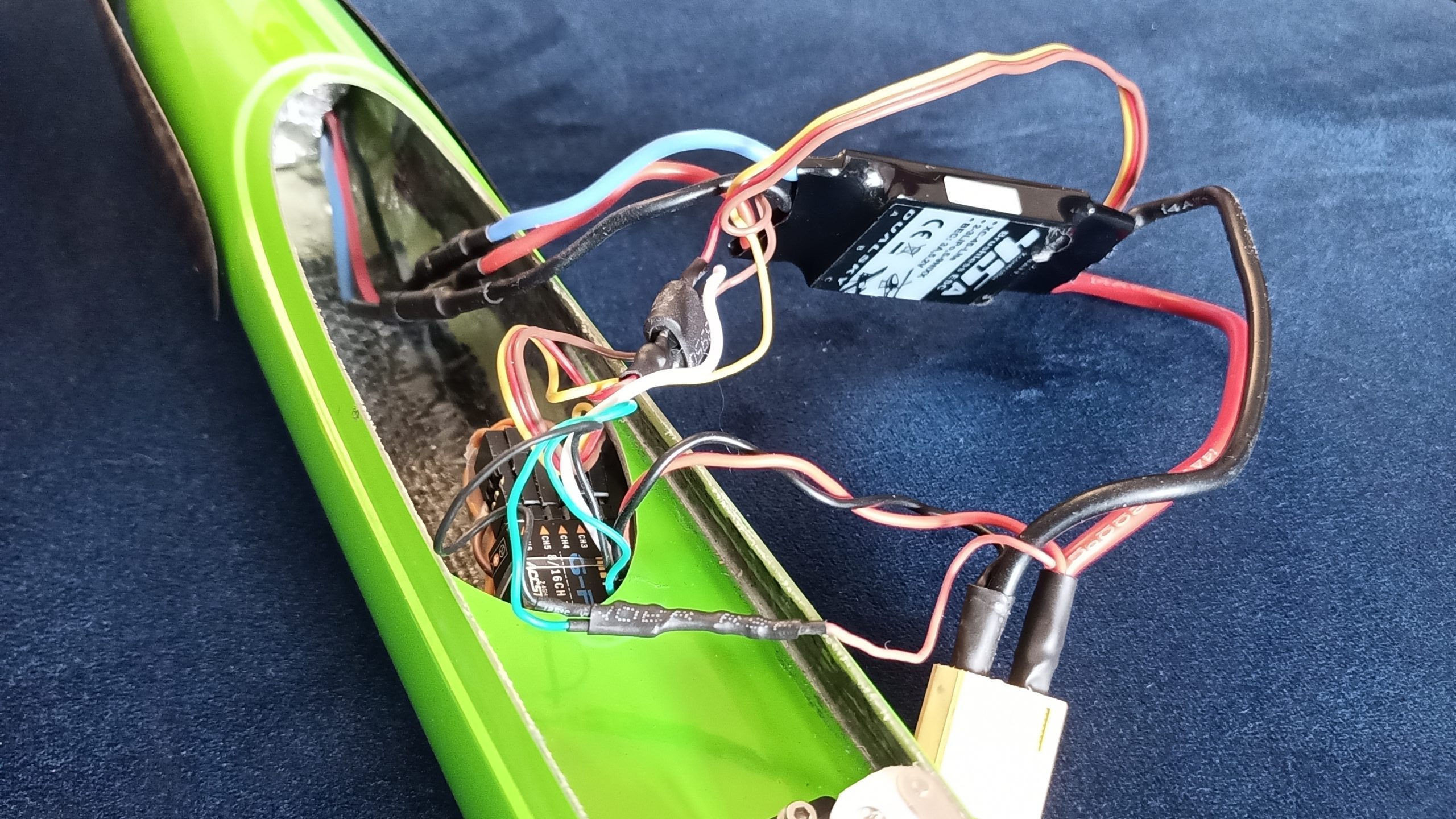
I like redundancy … my classic setup:
– redundant BEC (one from the ESC, one with a 7.2V UBEC put in front of the wing joiner here)
– dual schottky diode creating the power redundancy – It allows also the HV servo to work at 7 Volts.
– redundant receiver (FRsky G-RX8 – 2.4Ghz + FRsky R9Mini 900MHz)
– telemetry for the battery level from the g-rx8 receiver A2 connector.
G-RX8 is also providing the telemetry VAlt+/- and VSpeed.
More info in another post here
Settings
Follow he settings provided by Ian Mason (http://willowracing.blogspot.com/p/harrier-build-notes.html).
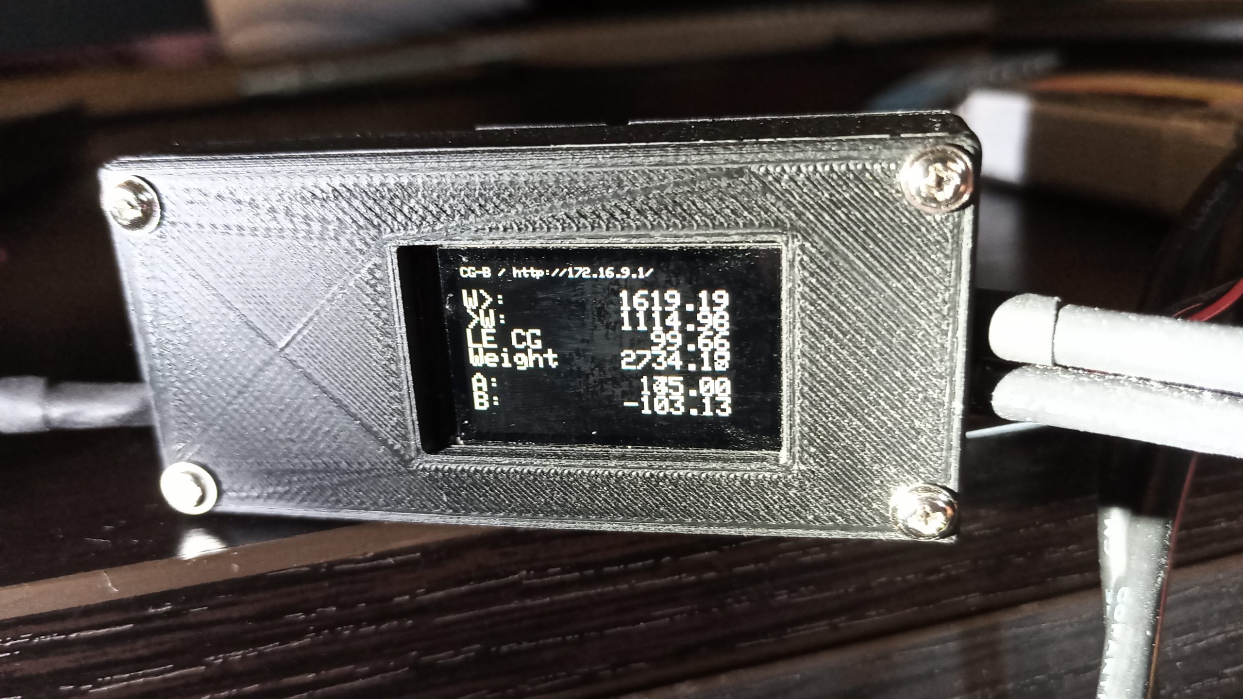
I am reaching a CG of 99.6mm from leading-edge with a very acceptable lead cylinder of 100 grammes (added behind the motor firewall).
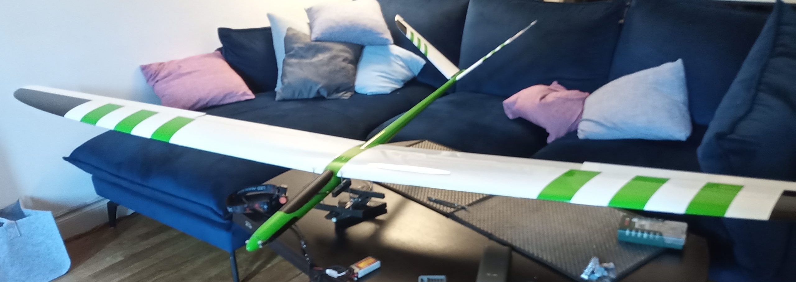
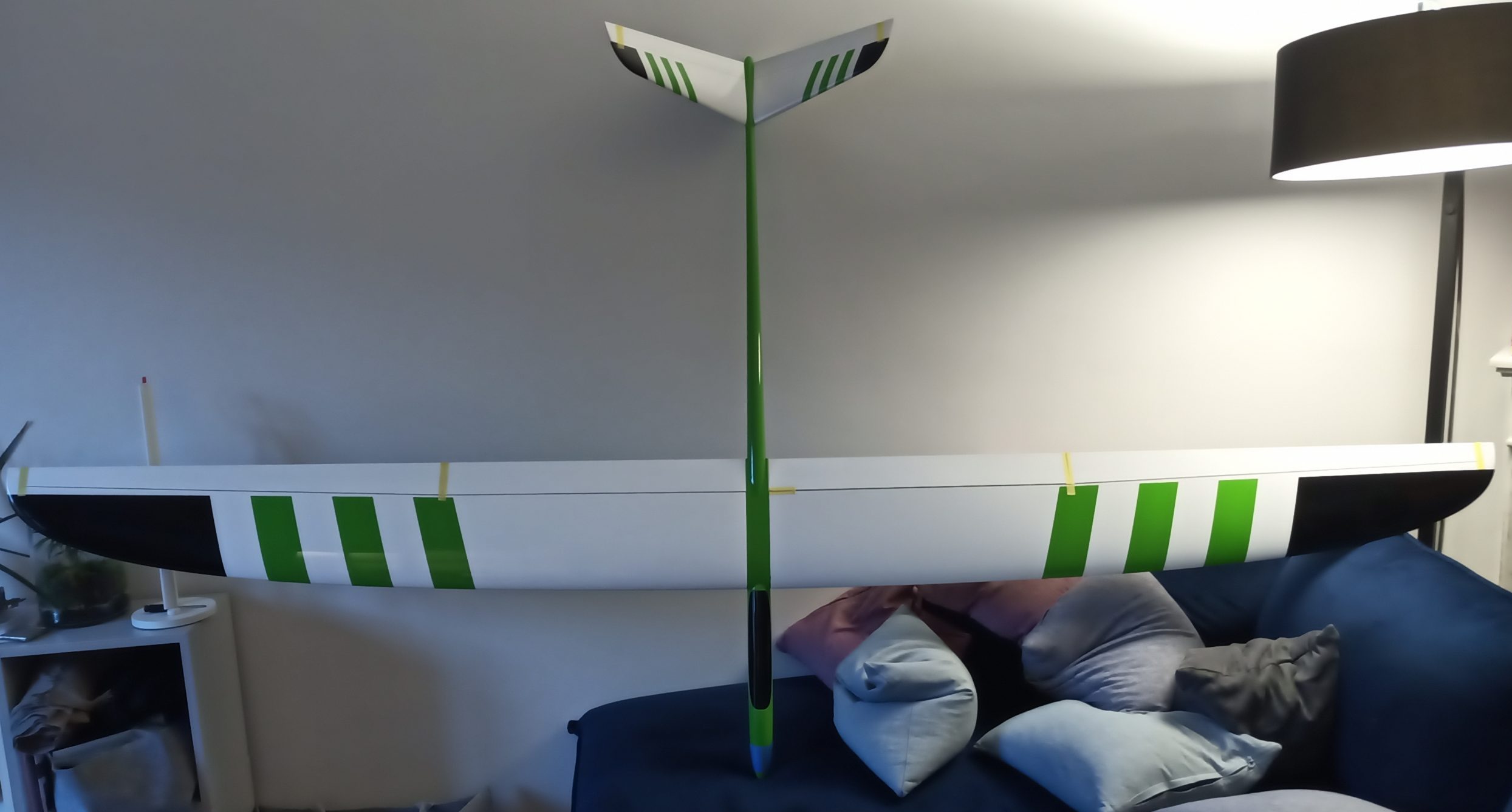
Final e-harrier ready to flight: 2.7Kg.